In order to meet the needs of high-push-to-weight aircraft engine development, countries around the world have adopted single crystal manufacturing technology in the turbine blade manufacturing technology of aerospace engines. The use of single crystal blades increases the temperature before the turbine by 55-80 ° C, increases the thrust by 7800 N, and has sufficient life and reliability. At present, in the United States and European countries, turbine blade single crystal manufacturing technology has made great progress. The world's advanced aero engines: such as the United States F119, the European four countries EJ200 and France's M88, etc. have adopted single crystal blades. Japan, South Korea, etc. are also actively developing new fighters using single crystal hollow blades. In order to catch up with the international advanced level and adapt to the development of high thrust-to-weight ratio aeroengines, China has carried out research on single crystal alloys as early as the 1970s, and successively developed first-generation single crystal alloys such as DD3 and DD8, and The blade single crystal manufacturing process has been studied to some extent. Shot peening technology has been widely applied to aero engines, civil engines, ships and other industries. Shot peening can effectively extend the service life of components, improve the life of the entire engine, and reduce costs.
As one of the key components of an aeroengine, high-pressure turbine blades directly determine the performance and safety of the engine. As the engine's operating efficiency increases, the temperature of the turbine inlet also increases, which makes the working conditions of the high-pressure turbine working blades worse, especially at the joint of the hoe. Therefore, how to improve the fatigue resistance of turbine blade boring head has become a hot topic and key issue in this field.
Test method
Shot peening is an important technique for improving the fatigue properties of materials. It is also often used for the reinforcement of high pressure turbine blades. However, at present, domestic research on shot peening of blade hoes mainly focuses on polycrystalline materials, while peening of single crystal materials is less. In this study, a new single crystal material was used as the matrix, and the bending fatigue life of the cast steel shot peened specimen and the ceramic shot peened specimen at 650 °C was compared, and the surface after shot peening was analyzed and evaluated. .
2. Test materials and methods
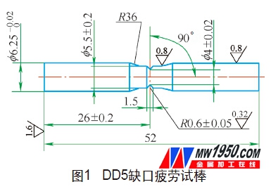
(1) Test material The test material is DD5 single crystal superalloy. The pure vacuum melting master alloy is used to remelt the alloy on a vacuum directional solidification furnace, and cast and make a single crystal test bar. The single crystal test bar was subjected to standard heat treatment, and the heat treatment system was 1300 ° C × 4 h air cooling + 120 ° C × 4 h air cooling + 900 ° C × 16 h air cooling. After the heat treatment, the test bar is processed into a rotary bending fatigue sample and a test piece of about 3 mm thickness by a process such as wire cutting, turning and grinding, wherein the specific shape and size of the rotary bending sample are as shown in FIG.
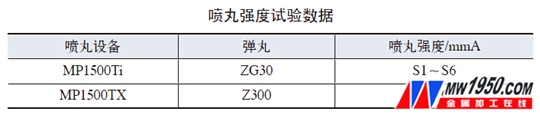
(2) Half of the shot peening test was carried out by cast steel shot peening on the CNC shot peening machine; the shot peening strength ranged from S1 to S6, and the surface coverage was 100%. Half of the samples were shot by ceramic shot peening on a CNC shot peening machine. The shot peening test pieces are all made of the international standard shot peening test piece type A. The shot peening strength of the test bars is shown in the attached table.
3. Test results and analysis
(1) Hardness distribution Figure 2 shows the effect of different strength shot peening treatments on the hardness distribution of the alloy surface using ceramic pellets. It can be seen that as the shot peening strength gradually increases from C2 to C4, the microhardness increases first and then decreases from the surface of the sample to the inside until the hardness of the inner matrix is ​​reached, that is, a hardened layer is formed on the surface of the sample after shot peening. At the same time, as the strength of shot peening increases, the depth of the surface hardened layer also tends to deepen.
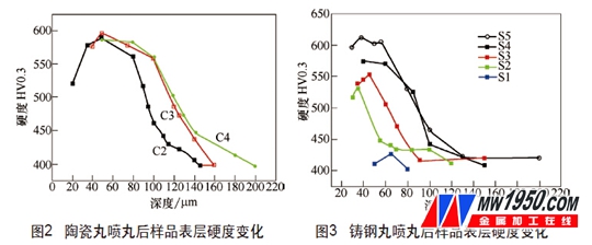
Figure 3 shows the effect of shot peening on the hardness distribution of the alloy surface using cast steel shots. It can be seen that as the shot peening strength increases from S3 to S4, except that the hardening effect is not significant under the S1 condition with lower shot peening strength, the hardness distribution under other conditions is consistent with the ceramic shot peening, and the hardness is second. After the surface reaches a maximum value, it gradually decreases to the level of the substrate. It also shows the law that the hardened layer is thickened as the shot peening strength increases.
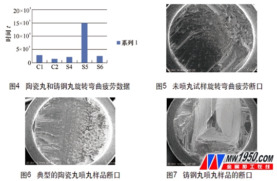
(2) Effect on fatigue performance The fatigue life results of ceramic shot peening and cast steel shot peening test bars at 650 ° C / 550 MPa are shown in Fig. 4. As can be seen from the figure, the shot peening strength will increase the fatigue life of the test strip, whether it is ceramic shot peening or cast steel shot peening. The fatigue life of ceramic shot peening is increased by 2 to 10 times, and the fatigue life of cast steel shot peening is increased by 4 to 10 times.
(3) Fracture bar fracture analysis Figure 5 shows the fracture of the sample without shot peening. The fracture has a typical fatigue fracture morphology, including crack initiation zone, crack propagation zone and instantaneous fracture zone. Cracks are found in the crack initiation zone on the free surface, which is mainly related to the instability of the slip zone on the sample surface.
Fatigue fracture of the curved sample. Although the fatigue fracture is also a typical crack initiation zone, extension zone and instantaneous break zone, the crack initiation position is different from that of the unpeened sample, and it is mainly generated on the subsurface of the sample.
Figure 7 shows the fatigue fracture of a rotationally curved sample of cast steel shot peened. The fractures are characterized by typical cleavage fractures. The crack initiation zone was not obvious. Cracks were observed inside the sample in the S5 condition shot, while no obvious crack source was observed in the S6 condition shot.
It can be seen from the comparison that the fatigue crack of the unpeened sample starts from the surface of the sample, and the fatigue crack source of the sample after the shot is moved to the secondary surface, and the fatigue crack source of the cast shot is moved to the inside of the sample.
4. Conclusion
(1) Whether the use of cast steel shot or ceramic shot peening can improve the surface microhardness, and has the same trend, from the sample surface to the inside, the microhardness is first reduced until the hardness of the internal matrix is ​​reached. In addition, both pellets showed a tendency to gradually deepen the depth of the surface hardened layer as the shot peening strength increased. Therefore, in terms of microhardness, the use of cast steel pellets and ceramic pellets can form a distinct hardened layer at a certain shot peening strength.
(2) Both cast steel shot and ceramic shot peening can improve the fatigue life, the fatigue life of ceramic shot peening is increased by 2 to 10 times, and the fatigue life of cast steel shot peening is increased by 4 to 10 times. The ceramic pill can reach the highest fatigue life when the shot peening strength C2; while the cast steel shot can reach the highest fatigue life at the shot peening strength S5. In comparison, the average fatigue life of cast steel shots is higher.
(3) From the fracture point, the fatigue crack of the unpeened sample starts from the surface of the sample, and the fatigue crack source of the sample after the shot is moved to the subsurface, and the fatigue crack source of the cast shot is moved to the sample. Internal, helps to suppress fatigue crack growth.
About the author: Yang Qing, He Shan, Meng Zhenwei, AVIC Shenyang Liming Aero Engine (Group) Co., Ltd.
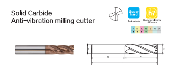
Milling Cutter Solid Carbide
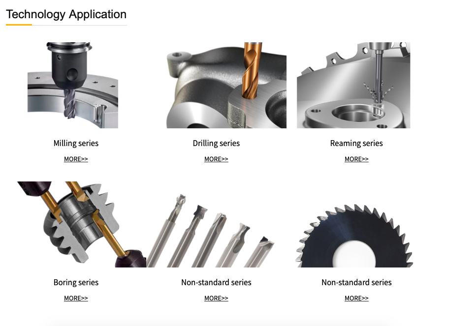
Carbide end mills are milling cutters made of solid carbide, which are used in CNC machining centers and CNC engraving machines. Carbide milling cutters are mainly divided into: solid carbide milling cutters, solid carbide straight shank groove milling cutters, solid carbide saw blade milling cutters, solid carbide auger milling cutters, solid carbide machine reamer milling cutters, solid end mills, solid ball end mills, solid milling cutters. Uses: Carbide milling cutters are generally used in CNC machining centers and cnc engraving machines. It can also be installed on an ordinary milling machine to process some harder and less complex heat-treated materials
Milling Cutter Solid Carbide,Solid End Mill,Solid Carbide End Mill Cutter,Carbide Tipped Milling Cutters
ROYI CNC TOOL TAIXING CITY CO.,LTD , https://www.royitools.com