
Abstract: The theory and method of non-contact measurement and positioning of line patterns by charge-coupled devices are discussed. A high-speed data acquisition of CCD signals using dual-port RAM technology and high-speed A/D is introduced. System and its applications. | ||||||||||||||||||||||||||||||||||||||||||||||||||||||||||
In industrial production and scientific experiments, the measurement or positioning of slits or filament diameters within a millimeter is often encountered. Traditional measurement methods use precision gages for measurement, which are slow, error-prone, and limited in application. The CCD imaging method is used to locate or measure the diameter of the filament, which has the advantages of high measurement accuracy, high speed, convenient use, easy connection with a computer, and automatic monitoring. | ||||||||||||||||||||||||||||||||||||||||||||||||||||||||||
| 1 Working principle Dual-channel CCD high-precision line measurement real-time monitoring system is mainly composed of two-way CCD camera and light source and circuit box. The functional block diagram of the system is shown in Figure 1. | ||||||||||||||||||||||||||||||||||||||||||||||||||||||||||
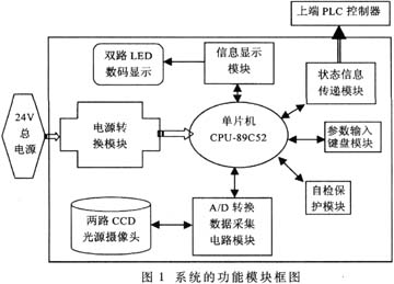 | ||||||||||||||||||||||||||||||||||||||||||||||||||||||||||
| The system uses TCD142D (2048-bit) linear array CCD device from Toshiba Corporation of Japan as the detecting component. The light source is uniformly irradiated on the positioning line of the paper to be tested, and the positioning line is imaged on the photosensitive surface of the CCD device by an optical system at a certain magnification, and the incident photons are arranged to be absorbed by a row of photosensitive cells, and a certain amount of photogenerated charges are generated at the same time. During photointegration, these photogenerated charges are stored in potential wells of respective pixels that are isolated from each other. During charge transfer, the photo-generated charges in each pixel are allocated in odd and even numbers, and are transferred to shift registers disposed on the upper and lower sides of the pixel, and then transferred to the output terminal under the control of the transfer pulse, thus being photosensitive. A line image is formed on the surface to realize one-dimensional scanning and signal reading of the object to be measured. The size of the CCD output signal is proportional to the intensity of the illumination. The amplitude of the output signal of the image part of the image is small, and the amplitude of the output voltage of the non-image part is large. Therefore, the line pattern forms a wedge-shaped concave waveform in the CCD output signal, as long as The number of cells occupied by the wedge shape in the waveform of the entire CCD output signal and its relative position are counted, and it can be determined whether the position of the paper has moved and its relative displacement. If it is within the error range, the upper computer can be notified to control the cutter to lower the knife. Otherwise, the upper computer can be notified that the knife cannot be cut and the error is displayed. The staff can adjust it until the paper position is correct. During the whole process, the system measures and displays the error in real time. When it is correct, it displays "0000". After the staff presses the confirmation button, the system will immediately notify the upper computer to cut the knife. The parameters of each module of the system are shown in Table 1. | ||||||||||||||||||||||||||||||||||||||||||||||||||||||||||
Table 1 System Module Parameter Table | ||||||||||||||||||||||||||||||||||||||||||||||||||||||||||
| ||||||||||||||||||||||||||||||||||||||||||||||||||||||||||
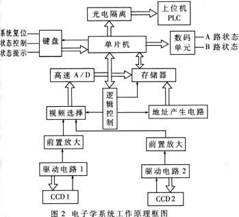
| 2 Hardware design The electronic system is mainly composed of CCD drive circuit, high-speed A/D conversion circuit, fast storage circuit, 89C52 single-chip system, keyboard input circuit, digital display circuit and power supply circuit. Its functional block diagram is shown in Figure 2. | ||||||||||||||||||||||||||||||||||||||||||||||||||||||||||
 | ||||||||||||||||||||||||||||||||||||||||||||||||||||||||||
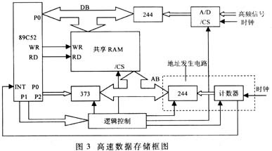
| Among the various parts of the circuit, the most important is the fast storage circuit of data, as shown in Figure 3. Obviously, the positioning of the lines, that is, the positioning of the paper, has become a problem of how many effective RAM cells are occupied by the line image portion and the start and end addresses of the cells in the RAM. | ||||||||||||||||||||||||||||||||||||||||||||||||||||||||||
 | ||||||||||||||||||||||||||||||||||||||||||||||||||||||||||
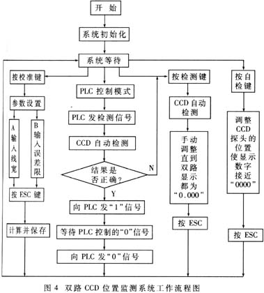
| 3 software design dual-channel CCD high-precision line measurement real-time monitoring system software flow shown in Figure 4. | ||||||||||||||||||||||||||||||||||||||||||||||||||||||||||
 | ||||||||||||||||||||||||||||||||||||||||||||||||||||||||||
| Since the system is used for on-line measurement, the detection device is installed on the cutting device, and each time there is a certain vibration when the knife is cut down, there is a certain error in the processing and assembly of the mechanical structure, and the illumination source is not completely uniform, which can affect the system. measurement accuracy. In order to ensure the system's accuracy, stability and ease of use, the following main measures have been taken on the software: (1) System calibration After the working distance of the system is determined, in order to determine the actual size of the target with the number of pixels N occupied by the target image, the system needs to be scaled before the formal measurement. The calibration method should be: first place a standard module of a known size at the target position, and then determine the number of CCD pixels occupied by the image of the module by reading the digital quantity, thereby obtaining the target CCD image in the system. A proportional coefficient K. The K value is usually stored in the computer, and the actual size of the target can be calculated by the software at any time while continuously measuring the target. This method is simple and straightforward, but since the influence of system error is not considered, the measurement accuracy is not high. In order to remove systematic errors in the measured values, a secondary calibration method can be used to determine the proportionality factor K in the system. If the systematic error is b, then the actual size X of the measured object and its corresponding number of imaging pixels Y are: X = KY + b, so two calibrations can be taken to determine the K and b values. After taking the K and b values ​​measured by the above secondary calibration method, the influence of system error on the measurement accuracy can be eliminated. It should be noted that the above two calibration methods only consider the calibration of the system when it is relatively static. For dynamic online measurement, computer correction should be taken according to the actual situation to improve the measurement accuracy. (2) Effective edge extraction To determine the range of the line image, it is necessary to determine a threshold value, which is the average value of the maximum and minimum values ​​of the output signal of the image formed by the line on the CCD. If the data value read from the RAM is below the threshold, the unit where the data is located is counted in the line range, otherwise it is not counted. Obviously this value changes with the intensity of the illumination light, not a fixed value. Instead of using a fixed threshold, each sample counts a threshold value that varies with the intensity of the illumination and the influence of the external environment as the starting point and ending point of the image edge, so that the image range can be effectively determined to avoid changes due to light intensity. The error caused. (3) Elimination of glitch noise Ideally, the analog signal converted by A/D should have only a low level at the line, other parts are high, and the rising and falling edges are steep. Since the sensitivity and accuracy of the CCD detecting element and the A/D converter are high, it is easy to convert the noise doped in the video signal together, as shown in FIG. | ||||||||||||||||||||||||||||||||||||||||||||||||||||||||||
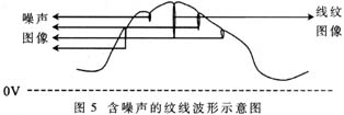 | ||||||||||||||||||||||||||||||||||||||||||||||||||||||||||
In addition to anti-jamming measures in the hardware, it is necessary to use software to eliminate glitch noise. Because the wedge of the image caused by the useful signal must be much larger than the difference of the wedge image caused by the interference signal, the method is to compare the difference between the maximum amplitude and the minimum amplitude of each glitch in the entire waveform, the largest one, It is the line pattern we are looking for. The position measurement accuracy of the whole system is ±9μm, the measurement range is ±5mm at the relative zero position, and the sampling rate CCD frame rate can reach 100Hz, that is, the sampling rate of 204.8kHz. The whole program includes system self-test, data sampling and processing, which takes about 350ms, and can complete multiple calibration functions such as zero calibration, size calibration, and automatic saving of error limits. | ||||||||||||||||||||||||||||||||||||||||||||||||||||||||||
:
Digital Tape Measure,Electronic Tape Measure,Laser Tape Measure,3 In 1 Digital Tape Measure
Yucheng Weisite Measuring Tools Co., Ltd , https://www.wsttools.com