
As a 3D CAD designer, when we do 3D CAD design, we often have the same situation: the same parts for any product or the same model. So when doing 3D CAD drawing, we want to put some
The components are used as a library, so that the previously drawn components can be called directly according to different parameters. I have used many other 3D CAD software before, and I also found that there are various brands of parts libraries on the network, but they are all known as national standards or international standards. I recently listened to my friend about Zhongwang 3D's 3D CAD/CAM software. I deliberately looked at how it was in the custom parts library. The result was unexpected.
Below I will share the first instance I made:
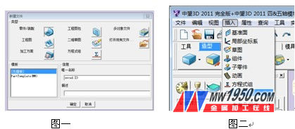
1. After opening the 3D, click the new icon (or “File†- “Newâ€), select “Parts/Assembly†under the newly created file, and define the file name in “Unique Nameâ€. As shown in Figure 1. Click OK to complete the new build.
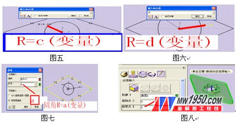
2. After performing the 3D editing interface, the first step of actually starting our custom part library is to find the “variable†option in the drop-down menu “Insertâ€, as shown in the red box in Figure 2. Clicking on it will bring up a dialog box for you to enter variables and expressions.
3. In the pop-up dialog box, enter the variable as 'a' and the input expression as '5', as shown in Figure 3. Click OK to complete
Create a function with a=5.

After the end, use the second step to the fourth step to input the variable to 'b', the input expression is '10'; the input variable is 'c', the input expression is '20', and the input variable is 'd'. The input expression is '40'.
Note: Careful friends may notice that in the middle 3D, the middle mouse button is a function to confirm and repeat the previous command, so after the operation defines the a variable, we can no longer go to the drop-down menu to find the variable option. We can use the middle of the mouse wheel to complete the previous command to complete the other three variables. So there is a chance that when you are working, you can see if you can use the mouse or other shortcuts, which will make it easier and faster for everyone to draw graphics.
4. At this point, we really started to draw CAD parts. Today I draw this part is a simple tool. Right-click in the drawing area, select "Insert Sketch", the [Sketch] property manager appears, select the XY plane (or the default mouse button) and click OK to enter the sketch drawing, using the line, circle (center, boundary <utilization Right-click tangent to select the diamond edge>) and other commands, draw a sketch as shown in Figure 4.
Since we have to do parametric design, when drawing CAD sketches, we must not think that the drawing is finished, and the four sides of the diamond shape are constrained by the construction type circle, so that it is all tangent-constrained; in addition, the diamond-shaped four sides do Equal constraint; at the same time, the constraint of the circle of the construction line is fixed ( note that if you have made relevant constraints when drawing, or when the system prompts excessive constraints, it means that it has constraints, this situation can continue the next step ).
After these constraints are completed, the sketching is not finished yet, because the parameterization is the most important piece, and the labeling has not been done yet, so the label is finished in the sketch, as shown in Figure 5 and Figure 6 (the radius of the circle of the solid line R = The variable c; the radius of the circle of the construction line R = d).
5. After ending the labeling of these two variables, we use the "rounded corner" command under "Geometry" in the sketch to give the diamond
The four corners are rounded, as shown in Figure 7. At this point, the sketch is finished, click to exit the sketch.
6. Click the [Stretch] button, the [Stretch] property manager appears, the contour P selects the 'Sketch 1' just drawn, the starting point S is set to '0', and the ending point E is set to <variable> b', as shown in Figure 8, click OK to end the stretch command. At this point, the part of the tool is drawn, and the next step is to make it a library.
7. In the drop-down menu "Properties", select the first option "Parts", and the following dialog box will pop up. First fill in the number in the first interface "Standard Properties", as shown in Figure 9, then use the left mouse button. Click on the running parameter. At this point, there is nothing in the running parameter. After clicking the first button in the upper left corner, it will automatically return to the drawing window. At the same time, you will be prompted at the command line below ("Specify label/variable" , or <click the middle button> to clear,)
Paint Brush,Wood Handle Paint Brush,Bend Handle Paint Brush,Wood Bend Handle Bristle Paint Brush
PRO-CHARGER CO., LTD. (VICTOR HERO HOLDINGS LTD, TIME VALUE LTD.) , https://www.pro-chargerco.com