
Today, insulated gate bipolar transistors (IGBTs) have become popular in power electronics and are used in many applications such as inverters, power supplies and electronic drives. The IGBT has a high reverse voltage (up to 6.5kV) and a switching current of up to 3kA. In addition to the power module itself, a key component in power electronics systems is the IGBT driver, which is an important interface between the power transistor and the controller. The choice of driver and the calculation of its exact output power determine the reliability of the converter solution. Insufficient drive power or incorrect selection may cause module and drive failure. The following summarizes some of the methods for calculating the output performance of a driver for switching IGBTs.
The gate charge reflects the characteristics of the IGBT
The switching characteristics of IGBT modules depend mainly on the semiconductor capacitance (charge) and internal and external resistance. Figure 1 is a schematic diagram of IGBT capacitance, where CGE is the gate-emitter capacitance, CCE is the collector-emitter capacitance, and CGC is the gate-collector capacitance (or Miller capacitance). The characteristics of the gate charge are represented by the input capacitances CGC and CGE, which are key parameters for calculating the output power required by the IGBT driver circuit. This capacitor is almost immune to temperature, but is closely related to voltage and is a function of the IGBT collector-emitter voltage VCE. This dependency is greatly increased when the collector-emitter voltage is very low, and the dependence is lowered when the voltage is high. When the IGBT is turned on, the characteristics of the IGBT are reflected by the gate charge. Figure 2 shows a simplified waveform of the gate-emitter voltage VGE, the gate current IG, and the corresponding collector current IC as a function of time from the IGBT turn-on to saturation. As shown in the IG=f(t) diagram, the conduction process can be divided into three phases. They are the charging of the gate-emitter capacitor, the charging of the gate-collector capacitor and the charging of the gate-emitter capacitor until the IGBT is fully saturated. The gate current IG charges the input capacitor, and the on and off characteristics of the IGBT are reflected by the voltages VGE and VCE associated with the charging process. During shutdown, the described process operates in the opposite direction and the charge must be removed from the gate. Due to the nonlinearity of the input capacitance, the input capacitance may only be applied to a certain range in order to calculate the driver output power. A more practical way to determine the output power of a driver is to utilize the gate charge characteristics.

Figure 1 IGBT capacitance
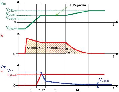
Figure 2 Simplified gate charge waveform
Next page
Metallographic Cutting Machines
Cutting is the first step of material analysis. The selection of cutting machine and cutting wheel must comply with the geometric size and material characteristics of the sample. The perfect metallographic cutting should avoid microstructure thermal damage and deformation, and preserve the necessary accuracy and efficiency.Hardness and ductility are the two main parameters for selecting the cutting wheel. The best choice of the cutting wheel depends on the size, hardness and ductility of the material and the equipment used. Trojan's cutting products speak with facts and the cutting process is simple, fast and accurate.

Metallographic Cutting Machines,Metallographic Cutting Equipment,Metallographic Cut-Off Saw Equipment,Metallurgical Sample Cutting Machine
TROJAN (Suzhou) Technology Co., Ltd. , https://www.trojanmaterial.com