
Abstract: The SEM analysis of the fracture morphology of a marine reducer bolt is carried out. Combined with the working conditions and stress conditions of the bolt, the mechanism and process of the fatigue shear fracture formation are analyzed, and the cause of the bolt fracture is inferred. And put forward corresponding solutions to provide an important reference for the safe operation of the machine and the optimization of structural design.
Key words : bolt; fracture; SEM analysis
Bolts used in ships are generally required to have high strength, high fatigue resistance, high reliability and corrosion resistance. While cleaning the circulating oil tank of a rear gearbox of a ship, several broken or detached bolts were found, which came from the large gear web. The author analyzes the stress of the bolt and tests the fracture morphology to infer the cause of the bolt breakage and proposes corresponding improvement measures.
1 Bolt chemical composition and hardness
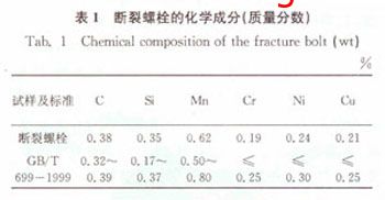
Sampling from the broken bolts for chemical composition analysis, the results are shown in Table 1, in line with the technical requirements of 35 steel in GB/T699-1999 standard. The bolt material is a high-quality carbon structural steel with good comprehensive mechanical properties, high strength, and certain plasticity and toughness.
The bolt has an accuracy grade of 8.8 and a specification of M8×25mm. After quenching and high temperature tempering, the microstructure is tempered sorbite, and its hardness is tested to obtain a hardness value of 26-31HRC, which satisfies 8.8. Technical requirements, it can be speculated that the bolt breakage is not caused by improper heat treatment.
2 bolt condition and force analysis
The broken bolt is shown in Figure 1. The fracture is at the second and third turns of the root of the thread. When the gearbox was disassembled, it was found that the bolts were placed on the large gear web and the bolts were placed at intervals with the pins. The installation arrangement is shown in Fig. 2.
The bolt is subjected to tensile stress and torsional shear stress during operation of the machine. The yield strength of the bolt material is σs = 640Mpa. Under the assumption that the bolt is under normal stress, the bolt strength is calculated and checked. The stress σ of the bolt is far less than its allowable stress. Therefore, the design of the bolt is also satisfied. For normal use, the material is used correctly, that is, under normal conditions, the bolt will not be overloaded and broken.

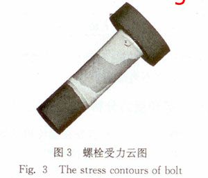
Under abnormal conditions, that is, if the stress concentration at the root of the bolt is serious, and the bolt is unevenly stressed and the load is skewed, the stress cloud diagram of the bolt calculated by the finite element software ANSYS is shown in Fig. 3, which is obtained from the figure. The maximum stress of the Von Vises of the bolt is 298 MPa, and the allowable stress of the bolt is not exceeded. Therefore, it can be determined that the cause of the bolt breakage is not caused by insufficient strength.
3 bolt fracture analysis
In order to further find the cause of the fracture, the oxide film on the fracture surface was ultrasonically cleaned, and then the fracture morphology of the bolt was observed under a scanning electron microscope.
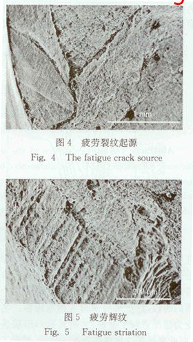
It can be seen from the scanning electron micrograph of the fracture of Figs. 4 and 5 that the fracture form is a fatigue shear fracture [1], so it can be judged that the bolt is a fatigue fracture. Figure 4 shows the origin of the fatigue fracture, which is at the thread groove, which is generally the stress concentration area due to the machining process. The initial stage of the origin of the crack is also called phase I, and the crack propagates to the middle. Figure 5 is a typical characteristic of fatigue fracture. These fatigue lines are the result of repeated shearing action.
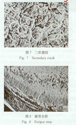
The fatigue fringe shown in Fig. 6 is the region of the high and low undulations left behind the crack front when the fatigue crack expands in the phase II. Each stripe is associated with crack growth in a load cycle. The density and width of the stripe are related to the load and stress levels being applied. The higher the frequency of the load, the lower the stress amplitude and the thinner the stripe. At the same time, as the crack propagates, the remaining load-bearing cross-section decreases, so the stress increases and eventually increases the crack propagation distance. The general direction of crack motion will be the macroscopic direction of crack propagation. It can be seen from Fig. 6 that the pitch of the stripes is about 10 μm, and the distance at which each of the cyclic cracks advances coincides. The scallop pattern shown in Fig. 7 is a secondary crack.
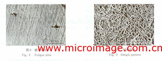
As can be seen from Figure 6, there is a significant fatigue step, which is the final stage of fatigue crack propagation, also known as Phase III, which is the final overload fracture. In stage II, when the crack propagates to this point, the residual support material is insufficient to withstand the load of the next cycle (or several cycles) and is usually broken. That is, in the project where the crack is expanding, the effective bearing area is also decreasing, and the stress is becoming larger and larger. When the stress exceeds the breaking strength of the material, the last one-time instantaneous break occurs. The fatigue fracture morphology presents a coarse river pattern, which also indicates that the bolt is subjected to torsional shear stress.
The morphology of the fracture surface depends on the fracture mechanism, as seen from the scanning electron micrograph of Figure 9, which is a distinct dimple feature, which also indicates that the material is shear failure. Due to the internal separation of the material, voids are formed, and the voids constitute the fatigue nuclei of crack initiation, and the voids gather, and then jointly develop into fracture surfaces, thereby causing brittle fracture. The voids of the bolt material are formed at the second particles, where the germination of the voids may be due to the depolymerization of the particles at the basic interface or due to the shedding of the particles. Some of the particles are located in the dimples of the matching fracture surface, or the particles fall off when separated, so some of the dimples in the fracture microstructure are empty.
The shape and size of the dimple are directly related to the size, shape and distribution of the second phase particles, and there are larger particles in the larger cavity, so it can be inferred that there is inclusion in the material. The bolt material belongs to carbon structural steel. The carbon and other elements in the steel may form brittle metal compounds. These brittle compounds are inconsistent with the elastoplastic deformation at the basic interface, which may cause stress concentration and fatigue at the edge of brittle inclusions. Cracks, which reduce the fatigue strength of the steel. The larger the size of the brittle inclusions, the more the particles, the greater the hazard. Therefore, for such steels for bolts subjected to alternating loads, the number of non-metallic inclusions must be strictly controlled.
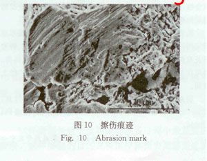
The scanning electron micrograph of Fig. 10 also shows that there are scratches on the surface of the fracture, indicating that the two sections have rubbed against each other after the bolt is broken. According to the analysis, since the broken bolt is applied to the gear plate, there is vibration shock during the operation, and the scratch marks on the surface of the bolt fracture are caused by vibration shock during the operation of the machine. On the other hand, it is also indicated that under the condition of vibration shock, the bolt is easy to loose, and the load of the un-loose bolt is increased. This load may be the lateral load due to the inertial force, so that the shear stress of the bolt is increased. Large, once it is greater than its shear strength, it will break. Therefore, it is speculated that the breakage of the bolt may be related to the vibration shock during the working of the machine.
4 Analysis and discussion
The composition, hardness and heat resistance of the bolts were found to meet the requirements of the technical specifications. Under normal conditions and harsh abnormal conditions, the bolt stress was also found by checking and calculating the bolt strength. It is much smaller than the allowable stress, and it is inferred that the breakage of the bolt is not caused by insufficient strength.
The inspection found that the pre-tightening force of the bolt was small when the bolt was installed, the bolt was loose before the fracture, and the scratch on the surface of the fracture surface caused by the vibration of the machine during the operation, so the breakage and pre-tightening force of the bolt were too small and the machine It is related to the looseness caused by vibration.
Through the SEM observation and analysis of the fracture morphology, combined with the bolt stress and working conditions, it can be found that the failure form of the bolt belongs to the fatigue shear fracture, the crack originates from the thread groove, and then develops with each cycle of the load. , eventually exceeding the critical value of the toughness of this material, and then expanding unsteadily leading to fracture.
5 Conclusions and recommendations
(1) Due to the insufficient pre-tightening force of the bolt, the root of the bolt is continuously subjected to external impact, and the inclusions in the bolt material cause fatigue cracks, and finally breakage occurs.
(2) Appropriately increase the pre-tightening force of the bolt to avoid loosening of the bolt under vibration and shock conditions.
(3) Improve the surface roughness of the bolts, and appropriately increase the radius of the transition fillet to reduce the stress concentration, thereby slowing down the process of fatigue fracture.
(4) For steels for bolts subjected to alternating loads, the number of non-metallic inclusions must be strictly controlled to improve the fatigue strength of the steel.
Electric Tools,Electric Hand Drill,Electric Cordless Impact Drill,Powered Electric Cordless Drill
Shijiazhuang Longshu Mechanical & Electrical Equipment Trading Co., Ltd. , https://www.lsjgbearing.com