
1.1 Experimental purpose
(1) Introduce the calibration and measurement usage of the iBolt intelligent bolt system;
(2) Verify that the iBolt intelligent bolt system is calibrated using the tension method and the measurement accuracy under the twisted pull state;
1.2 Experimental principle
When the bolt is in the free state, there is no pre-tightening force inside the bolt. When the bolt is in the tightened state, the bolt will be deformed due to the pre-tightening force. Therefore, the deformation of the bolt is ΔL, and the iBolt intelligent bolt system is based on ΔL. The mathematical relationship between the preload force F and the preload force F is calculated. The mathematical relationship is as follows:

(1)
Where F is the pre-tightening force of the bolt; E is the elastic modulus of the bolt material; S is the bolt cross-sectional area; ΔL is the deformation amount of the bolt; and L is the clamping length of the bolt pair. According to formula (1), the intelligent bolt system calculates the pre-tightening force F of the current smart bolt based on ΔL.
The intelligent bolt system transmits and receives ultrasonic pulse electrical signals, measures and calculates the time difference between the transmitted and echo electrical signals. When the bolt is in the free state, the time difference between transmitting and receiving electrical signals is T0. When the bolt is in the tightened state, the time difference between the bolt transmitting and receiving electrical signals is T1, thereby the time difference between the transmitting and receiving of the electric signal and the deformation of the bolt. The relationship between the bolts is obtained, where v is the propagation velocity of the mechanical longitudinal wave in the bolt. Finally, the pre-tightening force of the smart bolt in the current state can be obtained by the intelligent bolt system according to ΔL and combined with the formula (1). Schematic diagram of the measurement principle of the intelligent bolt system: Figure 2.1

Figure 2.1 iBolt intelligent bolt system measurement principle
The phenomenon that the ultrasonic wave velocity changes with the change of the stress state is called an acoustic elasticity phenomenon. This phenomenon exists both in the elastic range and in the nonlinear stress-strain range. [ 1 ] When the atoms inside the material are pressed together by compressive stress, experiments show that the elastic modulus becomes larger, and when the tensile stress of the atom is pulled apart, the elastic modulus becomes smaller, which indicates that the stress and The relationship between strains is non-linear. When ultrasonic waves propagate inside a stressed material, the effect of stress and strain on the ultrasonic velocity will change as the elastic constant E changes. Experiments show that the wave velocity variation of ultrasonic waves is linear with the magnitude of stress in both the elastic range and the nonlinear range of the material [ 2 ].
Based on this principle, the same batch of bolts can be extracted from one to be calibrated to obtain only the stress compensation coefficient (linear coefficient between ultrasonic wave velocity change and stress) related to the material. Then the other bolts of the same batch can be used to correct the stress and calculate the correct elongation and preload.
the second part  Experimental materials and equipment
M12x135mm (10.9 grade) bolt fine teeth (1.25) thread 16;
One iBolt intelligent bolt measuring system;
Universal tensile testing machine (0.5% measurement accuracy);
the third part  Experimental procedure
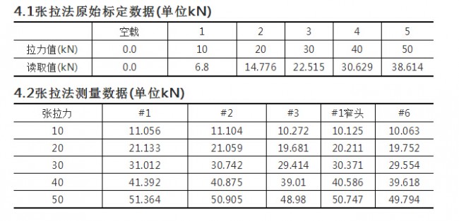
3.1 Tensile method to obtain the stress compensation coefficient of 10.9 grade material
(1) Establish a BQ grouping, select material class 10.9, and select 1# bolt for testing;
(2) Step-loading 10-20-30-40-50kN using a universal tensile tester, each stage of 20s;
(3) Record the pre-tightening force of the ultrasonic reading at each stage to form a pre-tensioning tension output force-ultrasonic measuring force calibration table;
(4) Input the calibration table formed in (3) into the iBolt intelligent bolt system, the BQ group of the material parameter 10.9, the effective stress cross-sectional area is 92.1mm^2 using the M12 fine thread check, and the system is based on the obtained stress. Calibration table, automatic calculation of stress compensation coefficient applied to BQ grouping;
3.2 Tensile method to measure the other 4 bolts of the BQ group
(1) Step-loading 10-20-30-40-50kN using a universal tensile testing machine, holding 20s per stage, and measuring the pre-tightening force data of the 2# bolt;
(2) Continue to measure 3#, 1# narrow head, 6# narrow head bolts with the method of (1);
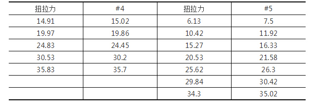
3.3 Twisting method to measure the other 2 bolts of the BQ group
(1) Use a torque wrench on the universal tensile testing machine to tighten to 10-15-20-25-30-35kN, and measure the pre-tightening force data of the 4# bolt;
(2) Continue to measure the 5# bolt with the method of (1);

Figure 3.1 Twisting pull operation real shot
the fourth part  Result data
4.3 tensile error percentage curve

According to the curve, after the preload force exceeds 50%, the iBolt measurement calculation error is within ±3%.
4.4 Twisting method measurement data ( unit kN)
4.5 Twisting method error percentage curve

According to the curve, after the preload force exceeds 50%, the iBolt measurement calculation error is within ±3%.
the fifth part  Conclusions and recommendations
According to the data of the fourth part, the following two conclusions can be obtained:
(1) In the elastic section of the bolt, the tensile method is used for parameter calibration. After the pre-tightening force of the tensile method and the twisting method exceeds 50%, the error percentage of the ultrasonic measurement can be controlled within ±3%.
(2) Twisting and tensioning methods The assembly of bolts does not affect the accuracy of ultrasonic measurement.
Therefore, in the actual measurement using the ultrasonic method, the first step can be calibrated by the universal tensile tester or the friction coefficient tester or the twist tester. The two methods do not affect the measurement accuracy of the ultrasonic method. .
  main reference
[1] Wang Yuguan. Acoustic elastic method and its ultrasonic measurement of stress measurement. Journal of Tongji University, 1996: 13-15
[2] MarkE. Froggatt and Sidney G. Allisom. Interrupted ultrasonic bolt load measurements using the PPLL system. IEEE TRANSACTIONS ON INSTRUMENTATION AND MEASUREMENT, VOL. 45. NO.1, FEBRUARY 1996:112-116
4014 Led Chip,4014 White Color Led Chip,White Color Led Chip,4014 Smd Led Chip
Shenzhen Huangtai Photoelectric Co.,Ltd. , https://www.huangtailed.com