
In the planning of the workpiece processing route, attention should be paid to the arrangement of the processing sequence, the structure of the parts and the condition of the blank, as well as the positioning, installation and clamping. There are mainly the following principles:
(1) The processing of the previous process does not affect the positioning and clamping of the next process.
(2) The processing steps are gradually carried out from coarse to fine, and the machining allowance is from large to small.
(3) The inner cavity is processed first, and then the outer shape is processed.
The processing technology and processing method planning is the detailed design of the implementation of the processing route. Specifically include:
(1) Select a suitable tool for different machining areas and machining processes.
(2) Select a reasonable tool path for different processing areas, processing types, and machining processes.
(3) Determine the error link and error control parameters related to programming to ensure the accuracy of CNC machining and the actual machining accuracy.
(4) Cutting process control (including backfeeding amount, feed rate, spindle speed), machining allowance control and advance and retract knife control.
(5) Safety control includes safety height and avoidance area.
The parameter setting is the specific implementation of the process. We will not repeat them here. The following is an example of the PROE/CAM application.
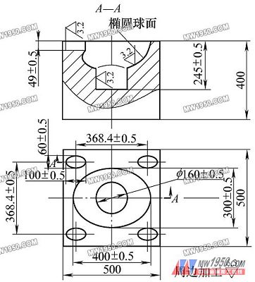
Figure 4
A simplified view of the part is shown in Figure 4. Through analysis: We decided to process the six elements on the ordinary machine tool, and then process the various elements on the CNC milling machine. First create a three-dimensional model (Figure 5).
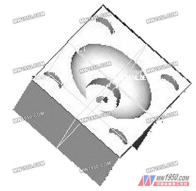
Figure 5
Process analysis and planning: (1) Processing object: elliptical spherical surface, Φ160mm hole, 4 elliptical holes.
(2) Tool setting: Φ40mm ball milling cutter is used for ellipsoidal spherical processing, Φ40mm vertical milling cutter is used for Φ160mm hole, and Φ20mm end milling cutter is used for 4 elliptical holes.
(3) Processing sequence: elliptical spherical surface → Φ160mm hole → 4 elliptical holes, which are divided into roughing and finishing.
Previous page next page
Solar Mounting System For Carport
Features:
1.HOT dipped galvanized or Q235 Steel, with excellent outdoor and marine environment protection
2.Compact for those smaller areas
3.Provides shading for your car or backyard needs
High strength galvanized steel structure, able to withstand 110mph wind, with Aluminum and Stainless steel supports
for solar panels.
4.Configuration: Single vehicle carport, with single cantilever side support gives aesthetically pleasing appearance.
Benefits of Using Honde Solar Carport Mounting Solutions:
Standard installations maintain 8'-6" minimum clearance
Three parking spots spanned between posts
Custom designs available
Foundation and installation options available
Readily tailored to fit different modules and parking lots
Industry-leading 20-year warranty on all our carport installations
Water control with decking available
No field welding, drilling, or other on-site fabrication
Multiple coatings options:
Hot dipped galvanized
Epoxy coated
Wide selection of pre-engineered designs:
Single-slope structures
Double-slope structures
Inverted design
Solar Panel Brackets,Carport Solar Mounting System,Solar Racking System,Mounting System for Solar Panels
Hebei Honde Plastic & Metal Co., Ltd. , https://www.foundation-system.com